
Professional Engineering
Engineering excellence at the heart of every project
We combine advanced 3D modeling, state-of-the-art analysis software and over a century of combined experience to design equipment and structures that perform in the harshest industrial environments — and to assess, rate and fix the ones you already have.
01Mechanical designs
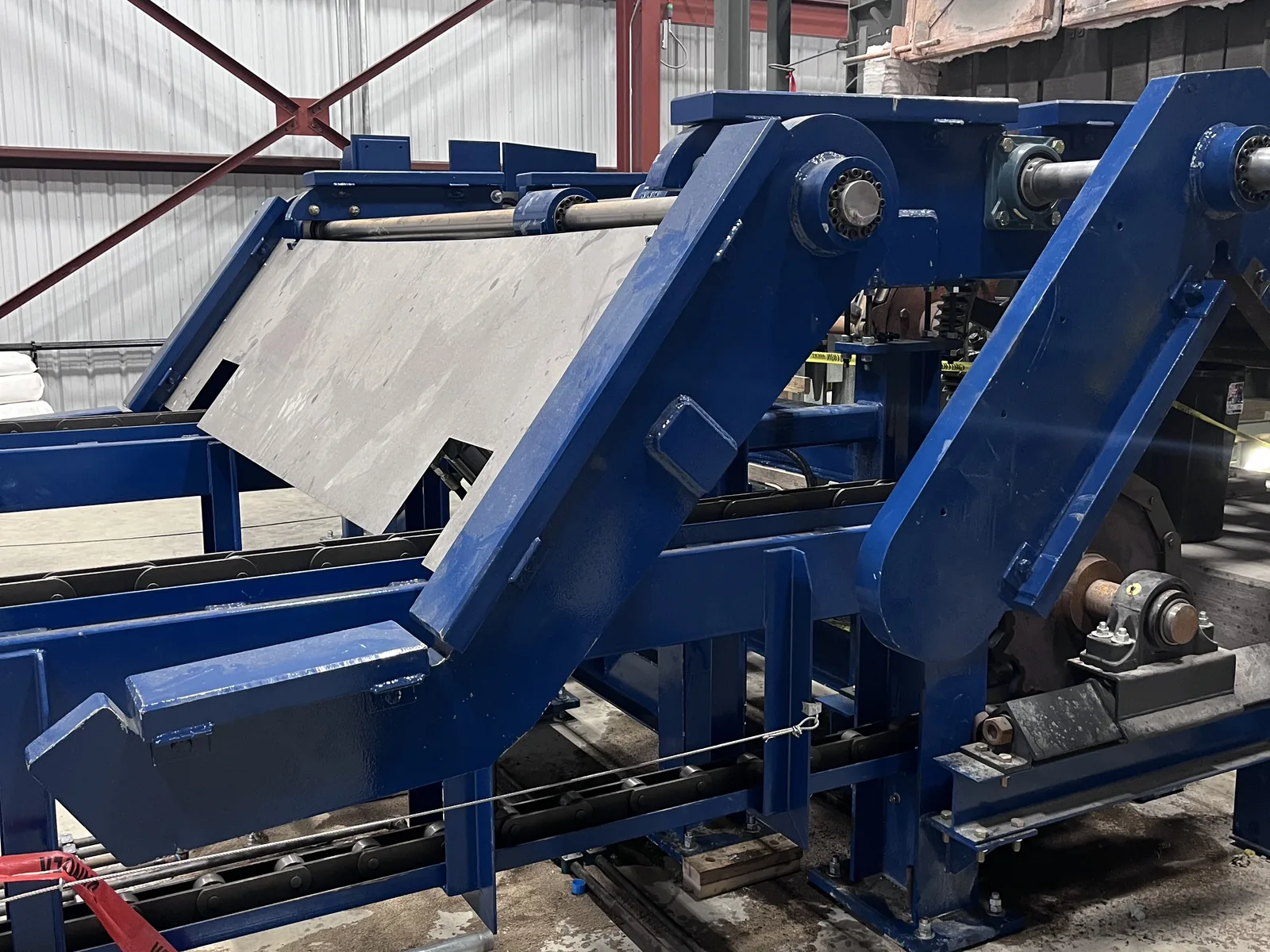
Machines built for the way your plant actually runs
We design custom machines and handling equipment for real plant conditions — heat, dust, shock loads and around-the-clock duty — starting from your process, not a catalog. Every design is modeled in full 3D, proven with analysis and handed over as drawings a shop can build from.
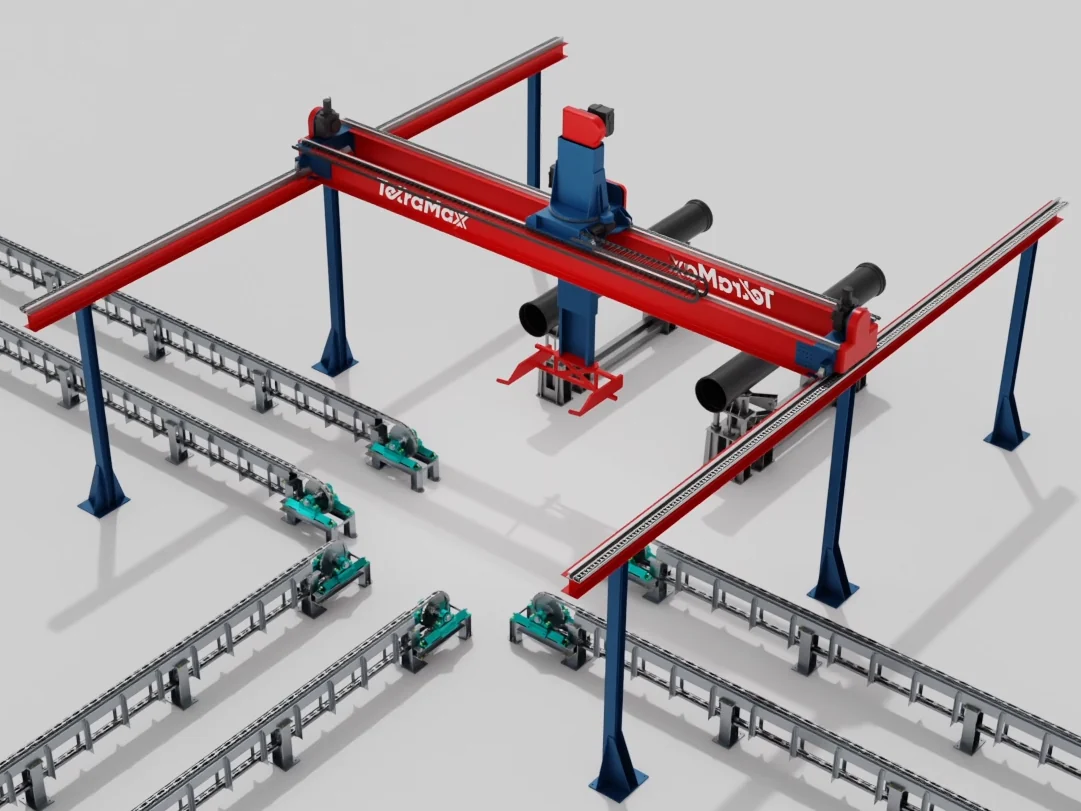
Recent mechanical designs
02Structural designs
Precision structures, fully modeled
Every structure we undertake is fully 3D modeled, which means fewer field conflicts, faster approvals and steel that fits the first time.
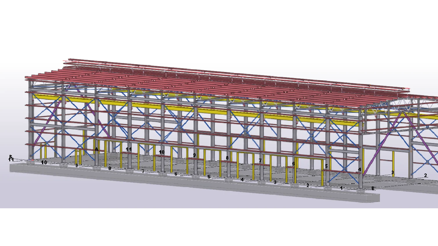
Recent structural designs — modeled, then built
03Foundations & concrete
Heavy foundations for foundry use
Equipment pits, machine bases, mats and piers are designed in Tekla alongside the steel they carry — reinforcement, embeds and anchor bolts modeled to the bar — so the pour and the erection fit each other the first time.
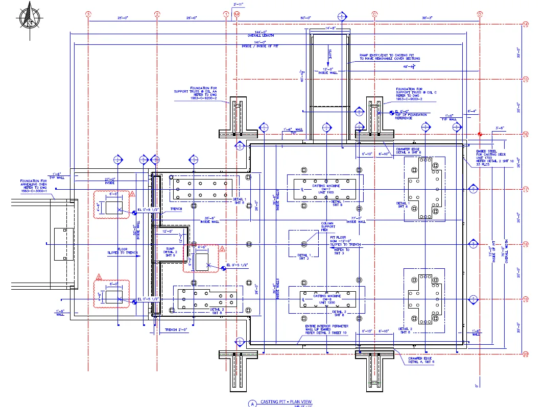
Recent foundation work
04Below-the-hook lifting devices
Rated, tagged and ready to lift
Every lifting device we design is engineered to ASME BTH-1 and B30.20, analyzed with FEA at rated load, and delivered with a stamped FEA analysis report, a capacity tag and a proof-load test procedure — so your crane crew never has to guess.
J-hook for a 40,000-lb charging bucket — designed to ASME BTH-1-2023 and B30.20, validated with FEA. Drag to orbit.
Recent lifting devices
05Existing equipment & structures
Know what your existing structures can carry
A mezzanine that has taken on new loads, a lifting beam with no paperwork, a building modified over decades — we inspect it, analyze it to current code and hand you a stamped answer and a plan you can act on, sequenced around your production schedule.
Tools & standards
How we get it right
Every design is modeled, analyzed and checked in purpose-built software before a licensed PE stamps it. These are the tools we use every day — and two examples of what they let us prove.
Onshape
Every machine and lifting device is modeled in full 3D, with drawings and BOMs driven from the model.
Tekla Structures
Steel modeled to the bolt, clash-checked, with shop and erection drawings generated from the model.
Tekla Structural Designer
Member design and code checks to AISC 360 on the same model the detailers use.
IDEA StatiCa
Component-based FEA for the special connections — heavy moment joints, odd geometry, unusual loads — where tabulated capacities aren’t enough.
SimScale
Solid FEA of lifting devices and machine parts under real loads and fatigue cases.
ANSYS Fluent
Flow, fume and thermal simulation for hoods, ducts and process equipment before anything is built.
Designed to AISC 360 / 341, ASME BTH-1 / B30.20 and ASTM material specifications · stamped by licensed PEs
Moment connection MC15 — HSS beam to column, end plate with stiffeners. Drag the slider to wipe the IDEA StatiCa stress results across the Tekla model — orbit either view.
Connection design
Every connection analyzed, not assumed
We design the connections, not just the members. Standard connections are designed and detailed in Tekla to AISC 360. The special ones — heavy moment connections, odd geometry, high or unusual loads — go through a full component-based finite element analysis in IDEA StatiCa, so we can see exactly where the stress goes instead of relying on tabulated capacities.
- Bolted and welded moment, shear and bracing connections
- End plates, stiffeners and doubler plates sized from the analysis
- HSS, wide-flange and channel members
- Prying, bearing, block shear and weld checks per AISC 360
- Connection drawings straight from the same model
CFD case study
Fume removal, proven before it was built
A plant needed the fumes from a hot metal ladle captured before they reached the operators. We modeled the workspace — ladle, air knife, suction hood and the enclosed bay — in ANSYS Fluent with a 500,000-cell mesh and ran the transient case for both the existing hood and our redesign.
The redesign was validated on screen, then fabricated — no trial-and-error on the plant floor.
Related services
Everything else we bring to a project
Need a machine or structure engineered?
Send us a sketch, a photo or a problem statement. Our engineers will tell you what it will take to make it real.